


Intro
As Signed Distance Functions start making it into mainstream and commercial applications, it's important to find replacements or alternatives to common things artists used to do in polygon-land. One such thing is displacement as a means to enhance or add detail to a shape. While much of what I'll say here applies to any kind of displacement pattern or SDF based "detail mapping", I'll focus on pure fBM style displacement in this article, the one we use to make procedural terrains for example (you might know it as "Fractal Noise" too). And the reason to find an alternative to it is that the traditional way of constructing and applying fBM (and displacement/detail) does not work well with SDFs. But, I've found an alternative that I think is competitive. So keep reading!
fBM SDF detail (not as a regular fBM displacement)
The problem
The problem with tradicional noise/fBM displacements on SDFs is this: the (regular, arithmetic) addition of two SDFs is not an SDF. Furthermore, the addition of an SDF and some other field/function (SDF or not) is also not an SDF (except for very carefully manufactured functions, that is). So, when adding a regular fBM, sine wave or any other displacement function to a "host" SDF, we don't get a valid SDF anymore (we violate the principle that the gradient of an SDF must have length 1.0).
That of course doesn't stop us from still trying, and we often do add arbitrary functions to our SDFs in the hopes of changing their shape. Sometimes we can achieve some level of success when done gently, but it all breaks rapidly when we push it a little bit. For example, when rendering SDFs through a raymarcher, adding a sine wave to a sphere can work for small amplitudes and frequencies, if the raymarcher happens to be designed to tolerate small deviations from true SDFs (always at the cost of performance). However it will sooner or later break as we make the sine wave larger or its wavelength shorter (since that pushes the length of the field's gradient away from 1.0 quickly).
That said, since we haven't really had an alternative for it, this method is still used for things that traditionally have been solved through displacement in polygon-land, such as the fractal terrains I mentioned in the intro; even though they don't work well or efficiently simultaneously. And this is unfortunate because fBM signals are very popular, well understood, widely implemented by all sorts of modeling, texturing and painting software, and widely used by artists. It's really a pity we can't simply use them with SDFs in a reliable manner.
Or can we?
A solution
Well, we know addition of functions doesn't work well with SDFs, so let's try to workaround it by redefining addition, see if we can repurpose and save fBMs.
The most important aspect of the addition in an fBM or fractal process, is not its arithmetic aspect or computation per-se. What's important is that waves of different amplitudes and wavelengths are being additively combined together, meaning, they sit on top of each other. That corresponds to how shapes in nature organize themselves too (hence the success of fBM in procedural modeling and texturing). So what we need is to define a new "addition" of SDFs that allows us to combine shapes together and grow them on top each other.
The "combining" part of our requirement is easy and we can do it with a simple union or smooth-union operation. That would be a min() or smoothmin() probably. In other words, as we generate SDFs of shorter and smaller amplitudes and wavelength, we can combine them with the "host" shape and to each other through the regular SDF union operations.
The "on top of each other" part of the addition can be achieved by making sure that these SDF layers (called "octaves" traditionally in standard/vanilla fBM implementations) only exist in the vicinity of the previous layer (or "host" object that we are applying our fBM displacement to). That way only the surface of our object will be augmented with the higher frequency detail, and no new surfaces will be created elsewhere.
One easy way to accomplish this is by clipping the SDFs layers against a slightly inflated version of the "host" SDF, ideally through a smooth-intersection to keep the smoothness of the final shape. That'd be a max() or smax() operator. Depending on the shape of the SDF layers we can still have flyovers (disconnected pieces of surface), so this is not a bullet proof method, but it works well in practice.
An implementation
So, let's put all these ideas together. First we need a random and smooth SDF to use as base function for our fBM. Since traditional 3D noise() is not a distance function (it's an Signed Field/Function, but doesn't measure distances), we cannot use it. Instead, we'll use an infinite but simple grid of spheres of random sizes. Spheres have simple SDFs, are isotropic and so they feel like natural candidates. Making an infinite grid of them is easy as well with some basic domain repetition. If we restrict the radius of our random spheres to be smaller than half the edge-length of the grid, then for a given point in space we only need to evaluate the SDF of the 8 spheres at the corners of the grid cell the point belongs to.
The code below is a possible implementation of such sdBase(), and to the right is a direct rendering of it:
float sph( ivec3 i, vec3 f, ivec3 c )
{
// random radius at grid vertex i+c
float rad = 0.5*hash(i+c);
// distance to sphere at grid vertex i+c
return length(f-vec3(c)) - rad;
}
float sdBase( vec3 p )
{
ivec3 i = ivec3(floor(p));
vec3 f = fract(p);
// distance to the 8 corners spheres
return min(min(min(sph(i,f,ivec3(0,0,0)),
sph(i,f,ivec3(0,0,1))),
min(sph(i,f,ivec3(0,1,0)),
sph(i,f,ivec3(0,1,1)))),
min(min(sph(i,f,ivec3(1,0,0)),
sph(i,f,ivec3(1,0,1))),
min(sph(i,f,ivec3(1,1,0)),
sph(i,f,ivec3(1,1,1)))));
}

sdBase(), an infinite grid of spheres with random radius
float sdFbm( vec3 p, float d )
{
float s = 1.0;
for( int i=0; i<11; i++ )
{
// evaluate new octave
float n = s*sdBase(p);
// add
n = smax(n,d-0.1*s,0.3*s);
d = smin(n,d ,0.3*s);
// prepare next octave
p = mat3( 0.00, 1.60, 1.20,
-1.60, 0.72,-0.96,
-1.20,-0.96, 1.28 )*p;
s = 0.5*s;
}
return d;
}

sdFBM(), adding 11 octaves of sdBase() together
So far this construction is identical to that of a basic fBM. However, instead of simply adding each layer n to the "host" SDF (passed as d to the function), we perform the modified "sdf addition": first we smoothly clamp the noise SDF n to the an inflated version of the host surface d. The inflation factor is 0.1*s in this case, but again, you should play with that. Just remember to make it proportional to s. The smoothness factor 0.3*s should also be subject to customization, but it's probably a good idea to keep it proportional to s as well, so we keep fractal detail at all scales.
The second part of our "sdf addition" is to combine the current layer n with the "host" sdf d. We do this, as we said, with a regular smin() operation with certain smoothness factor, 0.3*s in our case, which you should also experiment with and customize for your desired look.
In the image to the right side of the code snippet you can see what adding each one of these sdBase() layers does to the "host" SDF, a plane in this case. As you can see the process works great, and most importantly, the method produces a valid SDF, within the capabilities of smin() and smax() to do so, that is way better suited for raymarching and also for distance based lighting techniques (ambient occlusion, soft shadows) and collision detection than naive addition of fBM to the "host" SDF.
And the following is a video showing the fBM SDF construction, slightly modified for cosmetic reasons, together with some rendering of the resulting surfaces:
And the following is a realtime version of it in Shadertoy where you can see the technique in action, that comes with reference code so you can study and modify it directly: https://www.shadertoy.com/view/3dGSWR
LOD
As with most fractal constructions, one can easily band pass filter the geometry at construction time, and filter out detail that is not needed for a given pixel in the screen (or shadow-ray cone). To implement something like this, all we need to do is measure the maximum size the following sdBase() call can contribute with, which is given by the current scale factor s, and if it is below a given threshold th then break the loop. That's threshold th should be based on the size of a pixel in world space at the location of the fFM invocation, which you can compute easily with ray differentials. Basically,
float sdFbm( vec3 p, float d, float th )
{
float s = 1.0;
for( int i=0; i<11; i++ )
{
// evaluate new octave
float n = s*sdBase(p);
// add
n = smax(n,d-0.1*s,0.3*s);
d = smin(n,d ,0.3*s);
// prepare next octave
p = mat3( 0.00, 1.60, 1.20,
-1.60, 0.72,-0.96,
-1.20,-0.96, 1.28 )*p;
s = 0.5*s;
// lod
if( s<th ) break;
}
return d;
}
Variations
This fBM SDF technique accepts a million variations, of course. For example, sdBase() could be built with spheres that are not of random sizes but are instead located at random positions within the grid. Or both random sizes and random positions could be implemented, like in a "voronoise" pattern. They could also be smoothly blended together rather than being independent spheres. They could be arranged in tetrahedral simplexes rather than in a grid lattice for better performance too. Or the grid could be defined in polar coordinates rather than rectilinear, which can be useful if the "host" surface has cylindrical symmetry. Or it could be arranged in a logarithmic spiral or some other shape. Lastly, of course, we could replace the spheres with some other completely different primitive, such as cubes, torii or even ellipsoids to give the noise some anisotropic properties, Gabor-noise style.
Besides variations to sdBase(), there's plenty of room to play and be creative with the fBM SDF construction itself. For example, in the video above I displaced the grid by a small amount in each iteration, which helped increase the number of concavities in the field that looked like cliffs. Of course, the scaling factor could be a function of the SDF itself, or of space, or a combination. And lastly, the fBM could be using sdBase() in a subtractive manner rather than additively, effectively carving out fractal patterns from solids:
float sdFbm( vec3 p, float d )
{
float s = 1.0;
for( int i=0; i<7; i++ )
{
// evaluate new octave
float n = s*noiseSDF(p);
// subtract
d = smax( d, -n, 0.2*s );
// prepare next octave
p = mat3(0.00, 1.60, 1.20,
-1.60, 0.72,-0.96,
-1.20,-0.96, 1.28)*p;
s = 0.5*s;
}
return d;
}

Subtracting 7 octaves of sdBase() from a box SDF
Naturally the possibilities and endless and only limited by your imagination.
Problems
While the technique works great and has lots of advantages over adding traditional fBM signals to the "host" surface, it also comes with some problems. The main one is that it can sometimes produce "flyovers" - small pieces of surface that are disconnected from the "host" SDF in the case of additive fBMs (little holes will equivalently be created at undesired locations for subtractive fBM). This also happens with traditional 3D fBM as soon as we try to generate cliffs, so it's not a problem specific to the fBM proposed in this article. But it's nevertheless something we could try to alleviate. In some circumstances, it is possible to guarantee no flyovers will be generated, but making the clip (smax) and combine (smin) steps more conservative, at the cost of reducing the amount of detail on the surface.
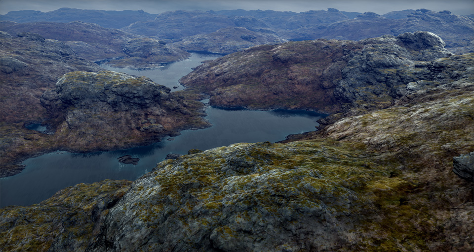
Conclusion
The technique is awesome as far as I can tell and produces beautiful pictures not only for terrains, but generally for growing/displacing any type of SDF detail on top of other SDFs.